| Lab Week Two
|
| Michelson-Morley Interferometer
OBJECTIVE: In this experiment you will learn about the operation of a Michelson interferometer and you will use the interferometer to measure the wavelength of light. REFERENCE: Krane, Section 2.2. THEORY: In any interference experiment with light, it is necessary to divide the light beam into two components, to cause these two beams to travel different paths, and then to recombine the two beams. Because of the different paths, the two beams may not be in phase when they are recombined - the wave crests of one beam may not line up with the wave crests of the other. If the difference between the two distances is a whole number of wavelengths, the beams will be in phase and the combined light intensity will be a maximum (constructive interference). If the distances are such that the two beams are completely out of phase, with the wave crests of one beam lining up with the valleys (troughs) of the other, the two waves cancel (destructive interference), and the intensity of combined light is a minimum. The Michelson interferometer achieves the division of the light using a half-silvered mirror - a mirror that reflects half of the light intensity incident upon it. The other half of the light intensity is transmitted through the mirror.
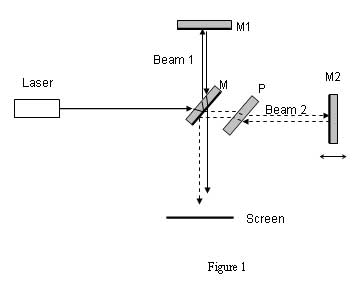
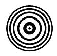
Figure 1 shows a diagram of the Michelson interferometer. Light from a laser is incident on the half-silvered mirror M. Half of the incident light (beam 1) is reflected from the rear surface of M, traveling back through M and toward mirror M1. The other half of the incident intensity (beam 2) is transmitted through M toward mirror M2, which is moveable. Beam 1 reflects from M1 and then again strikes the half-slivered mirror M. Half of beam 1 is reflected back toward the laser, but this light does not play any role in these observations. The other half of beam 1 is transmitted through M toward the screen. Beam 2 reflects from M2 and returns to reflect from M toward the screen (the portion of beam 2 that is transmitted through M back toward the laser is not important). The two beams recombine at the screen to produce the interference, which we observe as a circular pattern of bright and dark rings called interference fringes, as shown in Figure 2.
We often analyze reflection in plane mirrors by considering the virtual image produced behind the mirror due to the reflection. The reflection of beam 1 by mirrors M and M1 produces a virtual image of the laser a certain distance behind M1 (along the vertical axis of Figure 1). The reflection of beam 2 by M2 and M also produces a virtual image of the laser on the vertical axis, but if the two beams travel paths of different lengths the two virtual images will not be at the same location on this axis. We can then analyze the pattern on the screen by considering that the two virtual images of the laser can emit light that travels to the screen. The distance D between the two virtual images determines whether we see constructive interference (a bright region) or destructive interference (a dark spot) at the center of the screen. Suppose we move M2 by a distance d. The distance D between the two virtual images will change by 2d, because beam 2 travels twice along the path between M and M2. If the distance 2d is a whole number m of wavelengths, then each bright region on the screen will go to dark and then to bright again m times, corresponding to moving beam 2 relative to beam 1 by m cycles. The wavelength is then
PROCEDURE: 1. Carefully examine the interferometer and observe how light propagates through it. THE MIRRORS ARE FRONT-SILVERED - DO NOT TOUCH THE SURFACE OF ANY OF THE MIRRORS. 2. Tape a piece of paper to the screen and put a mark at the location of a clearly visible bright fringe. Note the reading on the micrometer dial. Turn the crank SLOWLY and count the number of times the bright region you marked changes to dark and back to right again. Count at least 20 changes and record the micrometer reading. 3. Return the dial to its original reading and repeat the measurement 2 more times. ANALYSIS: Calculate the value of the wavelength of light for each of your trials and find the average. Estimate the uncertainty of your average value. QUESTIONS: 1. Compare your value for the wavelength of the light with the accepted value for the red diode laser, XXX nm. Account for any differences. Does your value agree within the estimated uncertainty? 2. Explain the function of the plate P, which is known as the compensating plate. What does it compensate for? 3. Based on the explanation in terms of virtual images of the laser, you might expect that the condition for constructive interference would produce a uniformly bright region on the screen, rather than a series of alternating bright and dark regions in the circular fringes. Explain why the circular fringes occur. Imagine the two virtual images to be point sources emitting spherical wavefronts, and make a sketch in which one source is a few wavelengths behind the other. 4. Describe how you might use a Michelson interferometer to measure the index of refraction of air. Here is an applet that helps to understand the interferometer.
RELATIVISTIC MOMENTUM AND ENERGY
|
 Figure
2
Figure
2