After you create a VI, you can use it in other VI Block Diagrams as a Sub VI. When this is done, the Sub VI is considered as a lower-level VI inside of an upper-level VI. This reduces the number of Block Diagram icons, which simplifies and modularizes the VI. Sub VIs are much like functions or subroutines in conventional text-based programming languages.
In the following instructional example we will take the Slope Calculator VI you created in Module 2 and prepare it for, and utilize it as, a Sub VI.
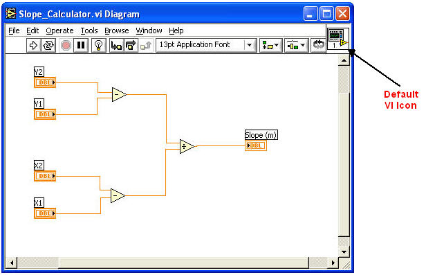
In order to customize the icon, pop-up on it's > Edit Icon.

The Icon Editor window appears:
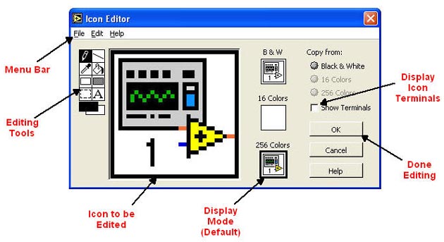
The largest area is where you see the default icon. This is where you will edit the icon using the Editing Tools (Explained in detail below). The Menu Bar contains standard editing options like Undo, Redo, Cut, Copy, Paste, etc. By Default the Display Mode is set to 256 Colors which is most commonly used (unless you are using a monochrome display). Show Terminals will display the icon terminals when checked, and when you are done editing the VI icon, select OK.
Icon Editing Tools
 |
Pencil - Draws and erases one pixel at a time. |
 |
Line - Draws straight lines. Hold down the shift key to draw vertical, horizontal or diagonal lines. |
 |
Dropper - Selects the color in the foreground of an element. |
 |
Fill Bucket - Fills a selected area with the foreground color |
 |
Rectangle - Draws a rectangular border in order to fill with the foreground color. If you double-click on the tool, it will frame the icon in the foreground color. |
 |
Filled Rectangle - Draws a rectangle bordered with the foreground color filled with the background color. If you double-click on the tool, it will frame the icon in the foreground color and fill it with the background color. |
 |
Select - Selects a rectangle area for editing. If you double-click on this tool and select Delete, it will delete the entire icon. |
 |
Text - Enters text into the icon editing area. If you double-click on this tool, you can select different fonts and font sizes. |
 |
Foreground/Background - Displays the current foreground and background colors. |
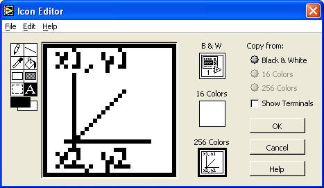
Below is an example of the Edited Icon:
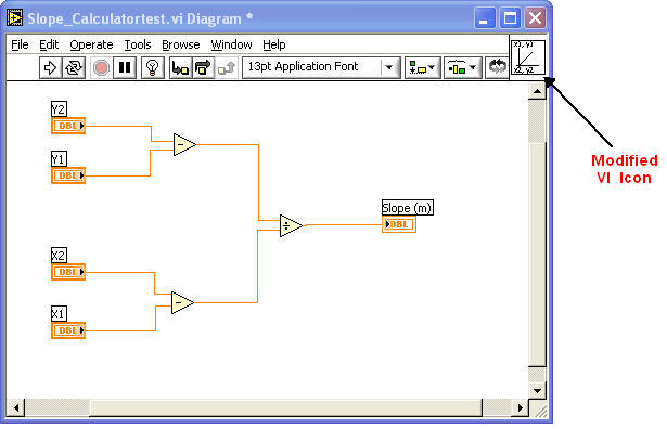
When you click OK, your VI window should look like this:
Assigning Sub VI Connectors
The next step in creating a Sub VI is to assign the icon connectors to the appropriate Front Panel Controls and Indicators. This will allow Controls and Indicators in the upper-level VI to wire to the Sub VI.
In the Front Panel, pop-up on the VI Icon > Show Connector:
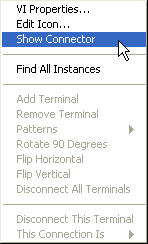
The Icon will change to show all of its connectors. In this case, our example looks like this:
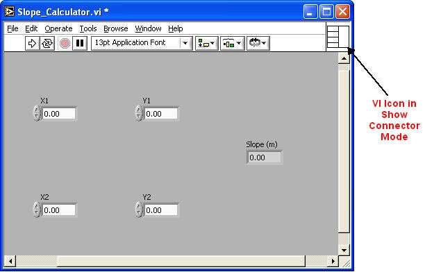
Notice that it has four connectors on the left and one on the right. The four connectors on the left will be the data-input wire hot spots for the four required Front Panel Controls. The connector on the left will be the data-output wire hot spot for the Front Panel Indicator.
Next, we will assign the connectors to the appropriate Controls and Indicators. This is done using the Connect Wire Tool on the Tools Palette. After you have selected the Connect Wire Tool, click on an icon connector and then click on it's respective Control or Indicator on the Front Panel. The icon connector should become dark. Repeat this process until all of the connectors have been assigned their respective Controls or Indicators. Be careful of the order of your selection. It will determine how the Sub VI is wired in the upper-level VI. When you are done, all connectors on the icon representation should be dark.
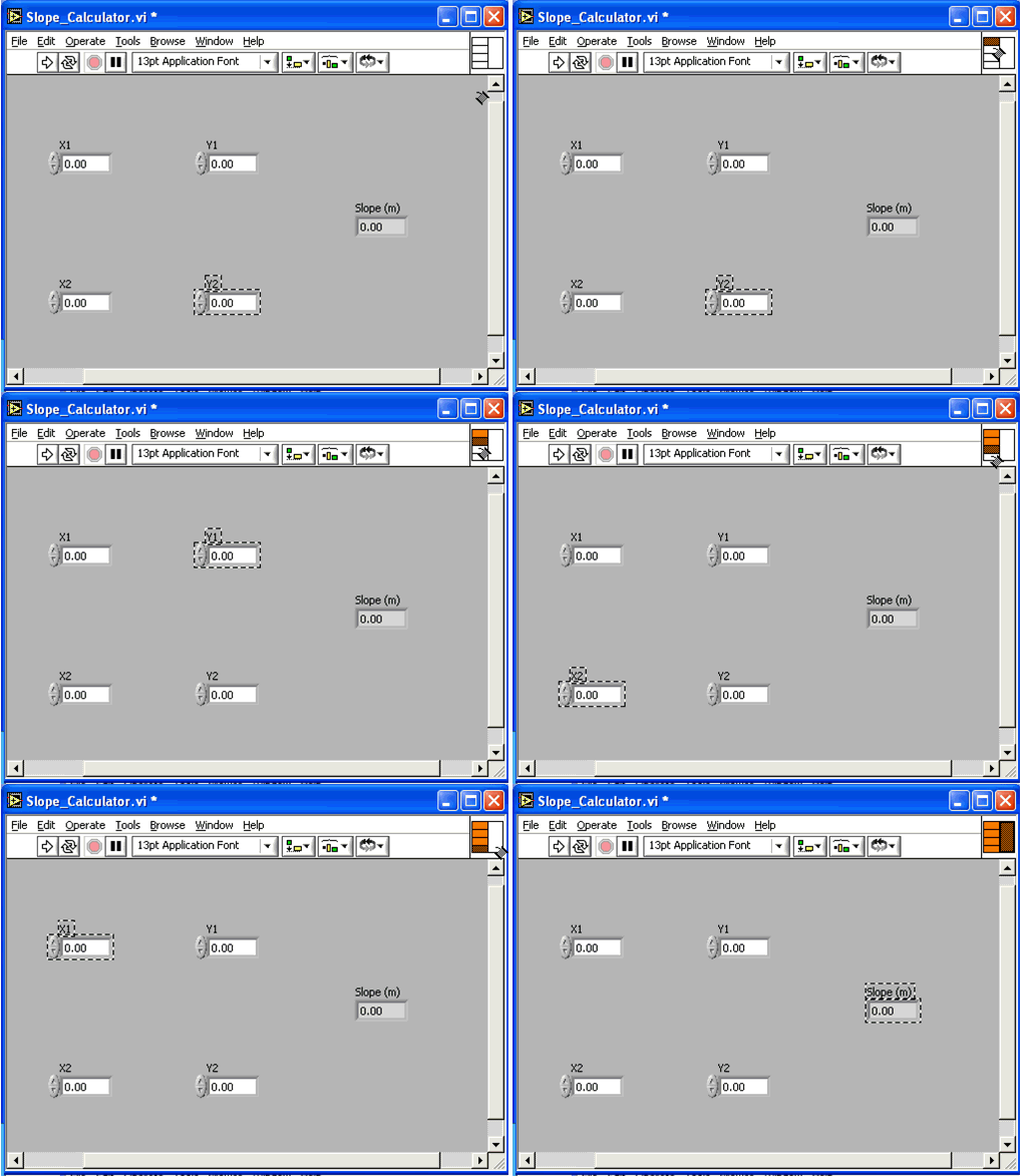
Make sure and Save your VI at this point.
Using a Sub VI
Using a Sub VI in an upper-level VI is fairly simple. In fact, you already have done this quite a few times in the past modules. In this example, we will employ the Slope Function VI in another VI called Slope_Function_Sub.vi
After you have created the upper-level VI and added all of the necessary Controls and Indicators, add the Sub VI to the Block Diagram by popping-up > Functions > Select A VI:
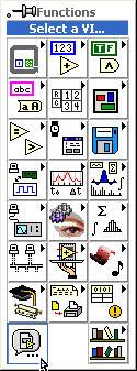
An Open File window will appear much like you see when you open any VI. Select the desired Sub VI and place it's icon on the Block Diagram. Then wire it's connectors to the appropriate Control and Indicator terminals:
To open a Sub VI from the Block Diagram, simply double-click on it and the VI's Front Panel and Block Diagram will open.

