
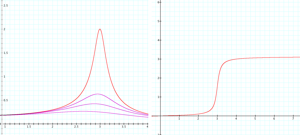
Plots of the amplitude and phase of the steady-state response of a damped oscillator to a sinusoidal driving force as functions of driving frequency.

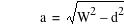

A,B – amplitude; k – spring constant; m – mass, b – damping constant; d – damping parameter; a – angular frequency; W – natural frequency


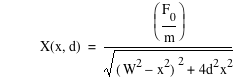


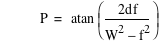
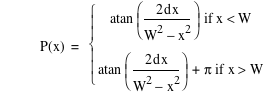

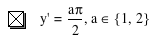



F0 – magnitude of driving force; f – frequency of driving force; X – amplitude of driven oscillation; P – phase of driven oscillation; R – resonant frequency
Author: David A. Craig <http://web.lemoyne.edu/~craigda/>
This file was created by Graphing Calculator 3.5.
Visit Pacific Tech to download the helper application to view and edit these equations live.