Qualitative analysis is a first step in solving second-order
ode. Qualitative
analysis can be used to verify numerical
and analytic solutions. Even if a
explicit formula for a
solution is known, qualitative analysis is useful, since
it
can give a visual picture of the behavior of solutions to
an ode.
In this section we consider qualitative analysis (or phase plane
analysis) of
autonomous second-order ode. These are differential
equations of the form:
![]()
Note that the differential equation does not contain the
independent variable t
explicitly. Our treatment here
is introductory.
Example

It is convenient to illustrate the procedure with an example. Consider the
ode
for a nonlinear
pendulum: y''=-(g/L)sin(y),
where g is the acceleration
due to gravity, L is the length
of the pendulum, and y is the angle between
the pendulum
and the vertical. For simplicity we set g/L=1. So the
differential equation is y''= -sin(y). To solve this problem completely
an
initial angle y(0) and an initial
angular velocity y'(0) must be specified.
Conversion to a System of ODE
The first step is to convert the original second-order
ode into two first-order
ode. Define v=y'. Then
v'=y''=-sin y. Hence, we get the following differential
equations:
![]()
![]()
The variable v corresponds to the angular
velocity of the pendulum. If initially
y(0) and y'(0)
are specified, then v(0)=y'(0).
Fixed-Points
Fixed points for systems of differential equations are
points in the y-v plane
where y'=0 and v'=0 simultaneously.
Fixed points are analogous to constant
solutions for
autonomous first-order ode. For our example the
fixed points
are the solutions to the equations:
![]()
![]()
Hence, the fixed points are
![]()
If initially (y(0),v(0)) is a fixed point, then the
solution is y(t)=y(0) and
v(t)=v(0). The system remains
at the fixed point. This is straightforward
to verify. For
example, if y(0)=0 and v(0)=0, then v(t)=0 and y(t)=0
is a
solution to the system of differential equations.
We can give a physical interpretation for the fixed points
for the nonlinear
pendulum. If y is an even power of
pi and v=0, the pendulum is in the resting
position as shown
in the figure below. Obviously, in the absence of
additional
forcing, the pendulum will remain in this position for all
time.
If y is an odd power of pi and v=0, the pendulum is
in the inverted position.
If the pendulum is perfectly
balanced it will remain in the inverted position
for all
time.


Vector Field
The system of differential equations for the nonlinear
pendulum defines a
vector field in the y-v plane.
At each point, the differential equation gives
y' and
v'. For example, at y=0 and v=1, we have y'=1 and v'=0.
These
derivatives indicate that v is not changing and
y is increasing at a rate of
1 unit per unit time. This
information is expressed by the vector (1,0).
The vector
indicates the direction of motion of the system
when y=0 and v=1.
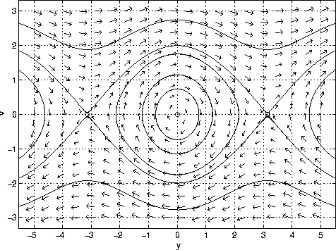
We can assign a vector for each point in the y-v plane
in this manner. This
is shown in the figure below. The small circle at
(-pi,0), (0,0) and (pi,0) are
the
fixed points.

Sketching Solutions
Solutions to the differential equation are tangent
to vectors at each point in
the y-v plane. This is shown
in the figure below. Notice that the solution
curves that
are plotted do not give y or v as a function of time. The
velocity
v is plotted as a function of
y.
The solution curves in the figure are 2pi periodic
in y. That means that the
structure in the interval
-pi<=y<=pi repeats itself in the intervals
pi<=y<=3pi, -3pi<=y<=pi, and so on.
A physical explanation can be attached to the solution
curves. The closed
curves centered about (0,0) correspond
to oscillations about y=0. The
curves at the top and
bottom of the figure correspond to whirling motion.
In this case the energy is sufficiently large for the
pendulum to turn
continuously in the clockwise or
counterclockwise direction. The top curve,
where y is
increasing, corresponds to counter-clockwise whirling.
The
bottom curve corresponds to clockwise whirling.
[ODE Home] [1st-Order Home] [2nd-Order Home] [Laplace Transform Home] [Notation] [References]
Copyright © 1996 Department of Mathematics, Oregon State University
If you have questions or comments, don't hestitate to contact us.