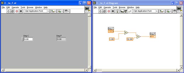
In this exercise, you will open the C to F VI you created earlier and prepare it for use as a Sub VI in the next tutorial.
Open the C_to_F.vi you created in Module 1
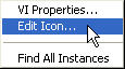
Edit the VI's icon
Pop-up on the VI's icon in either the Front Panel or Block Diagram > Edit Icon
In the Icon Editor Window, use the Editing Tools to modify the icon to look something like this:
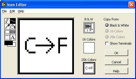
Click OK
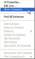
Assign the Connectors
In the Front Panel, Pop-up on the icon > Show Connector
With the Connect Wire Tool selected, assign the connectors to the appropriate Control and Indicator:
Save the VI under the same name and exit the VI