ADD OR SUBTRACT TUTORIAL
INTRODUCTION
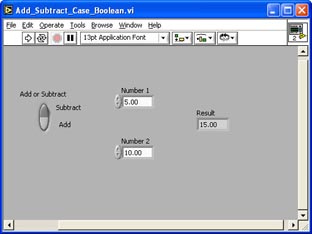
In this tutorial, you will create a VI
that utilizes a simple Case Structure. It is controlled
by a Boolean control to make the choice between adding
or subtracting two numbers. The numbers are inputted
through two Digital controls on the Front Panel. The
output data is wired to a Digital Indictor.
- Create a new VI
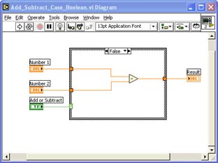
- Add a Case Structure to the Block Diagram
- Add a Vert Rocker Boolean Control to the Front
Panel
- Wire the Boolean Control's terminal to the selector
terminal on the Case Structure
- Add two Digital Controls to the Front Panel
- Add a Numeric > Subtract
function to the Block Diagram inside the Case
Structure
- Wire the Digital Control's terminals to the inputs
of the Subtract function (keep the terminals outside
the Case Structure boundary)
- Add a Digital Indicator to the Front Panel
- Wire the Digital Indicator's terminal to the
output of the Subtract function (keep the terminal
outside the Case Structure boundary)
- Go to the TRUE case of the Case Structure by
using the Case Structure pop-up menu or the menu
at the top of the Case Structure
- You should see an empty case with all controls
and indicators wired to tunnels on either side
of the Case Structure boundary.
- Add a Numeric > Add
function to the Block Diagram inside the Case
Structure
- Wire the Add function to the control and indicator
tunnels as shown above.
- Run the VI continuously and test the results
of both the subtract and add choices on the Front
Panel using different values in the Digital controls
- Stop the VI with Abort
- Save the VI as Add_Subtract__With_Case_Structure.vi
|