The Sequence Structure is used to control the data flow in a VI's Block Diagram. They are used to control the order of execution of nodes that are not data dependent on each other. The nodes within each frame are data dependent.
The output tunnels of Sequence Structures can only have one data source which, unlike Case Structures, has outputs that must have one data source per case. The output can come from any frame, but the data will not leave the structure until the last frame in the structure has completed it's execution. Data input is available to all frames.
Sequence Structures look like frames of film and, as with Case Structures, the frames are stacked on top of each other like a deck of cards. Also, as with Case Structures, you only see one frame at a time and you use it's pop-up menu or use the menu at the top of the structure to move between frames. The first frame is called frame 0 followed by frame 1, frame 2, etc. Data leaves the Sequence Structure only when the last frame in the structure is completed.
Creating a Sequence Structure is much like creating loops and Case Structures, where you drag a rectangle on the Block Diagram to define the size of the structure. To access the Sequence Structure, Pop-up in the Block Diagram > Structures > Sequence Structure.
When it is first placed, you only see one sequence with no menu at the top of the structure border. To add more frames, pop-up on the sequence boundary > Add Frame After
Sequence Locals
Sequence Locals are variables that allow you to pass data between frames of a Sequence Structure.
You create them by popping-up on the border of the Sequence Structure boundary. Sequence locals can be placed anywhere on the boundary. The data wired to the Sequence Local is available in all subsequent frames but is not available in any frames that precede the frame you created the Sequence Local in. You can remove Sequence Locals by popping-up on an existing Sequence Local > Remove
Below is an example of a Sequence Local that has been added to frame 1 of a three-frame Sequence Structure. The Sequence Local in frame 1 is wired to a node that will return data when that frame executes. Notice the direction of the arrow on the Sequence Local in that frame. It is pointing out which means that Sequence Local is a source of data. In frame 2, the Sequence Local is pointing in which means it is a sink for data. This means that the data from frame 1 is available to frame 2. Notice also that the Sequence Local in frame 0 is grayed out, which means the data from the Sequence Local in frame 2 is not available to frame 0 because frame 0 precedes frame 1.

Formula Nodes
Definition
A Formula Node is a box where you enter algebraic formulas directly into the Block Diagram. It is useful when an equation is complicated or has many variables. Below is an example of how you would implement y = x^2 + x + 1 with regular block diagram nodes:

It is much easier to use the Formula Node. Below is an example:
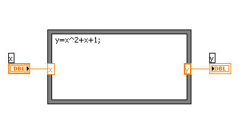
Creating a Formula Node
Pop-up in the Block Diagram > Structures > Formula Node. You must add an Input and an Output on the left and right vertical sides of the Formula Node's boundary. The nodes must also be named to match the variables used in the equation. Add them by popping-up on a vertical boundary > Add Input or Add Output. Label them correctly and wire them to the appropriate nodes.
Note: One or more of your Control and Indicator terminal representations may have to be set to Integer (I32)
You then type in your equation using the correct operators and functions. A semicolon always follows each formula statement.
Refer to Labview Help for a full listing.