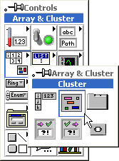
First, you place an empty cluster shell on the front panel.by popping-up on the Front Panel > Controls > Array & Cluster > Cluster and place the shell on the front panel.
The Cluster Shell can be resized "On-The-Fly" by dragging the size of the box as you place it on the front panel or by using the Resize function. Notice that only one node, the cluster node, appears on the block diagram.
Second, place your desired controls inside the shell.
Creating a Cluster Indicator
Creating a cluster of Indicators on the front panel is done exactly the same as above, except you place indicators in the cluster shell instead of controls.
Wiring Two Clusters Together
As shown in the animation below, you can wire control and indicator clusters together with just one wire. Notice the wire data type is cluster, and it is transferring three types of data (numeric, boolean and string) all in one wire.
.
Cluster Object Order
When Labview manipulates clusters of data, not only are the data types within the cluster important; the order of the components in the cluster is equally important. Cluster components have a logical order based upon the order that they were placed within the cluster shell. The first object based in the shell is component 0, the second component is component 1, etc. The order automatically adjusts if a component is added or deleted.
Changing Cluster Object Order
You can change the object order within a cluster by popping up on the Cluster Shell Border > Cluster Order.
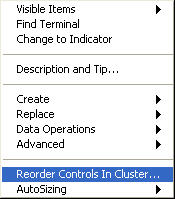
A new set of buttons replaces the toolbar and two boxes appear next to each cluster component. The white box next to a component shows it's current place in the cluster order. The black box shows the component's new place in the order.
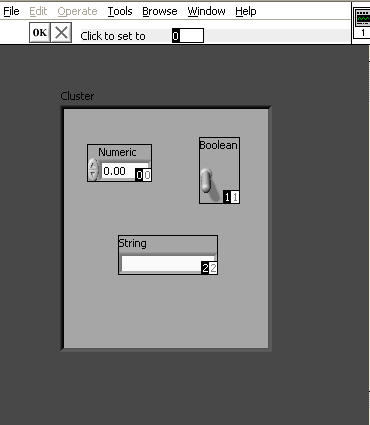
To set a cluster component to a new position in the order, first type the desired position number into the "Click to set to" field. Then click on the desired component. You will see the cluster order change not only in the component you are changing, but in the other components as well.
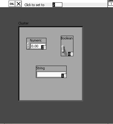
You can revert to the original settings by clicking on the Revert to Original button  . When you are finished, click on the OK button.
Assembling a Cluster on the Block Diagram Using the Bundle Function
You can assemble individual components into a single cluster using the bundle function on the block diagram. Pop-up in the Block Diagram > Functions > Cluster > Bundle.

Left-Drag the mouse downward on the control's border until you have the correct number of inputs and wire it to the components.

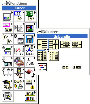
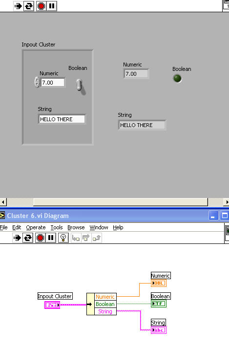
Disassembling a Cluster on the Block Diagram Using the Unbundle Function
You can use the unbundle function to disassemble the cluster back into its individual components. Pop up in the Block Diagram > Functions > Cluster > Unbundle.
Wiring it all Together
As shown in the animation below, the bundle and unbundle functions work together to assemble and then disassemble clusters.
Using the Bundle Function "Cluster of N Components" Terminal to Replace Cluster Objects
If you wire an existing cluster to the Cluster of N Components terminal of the Bundle function (on the top), you can wire new objects to the cluster that will replace one or more of the existing objects.
Shown below is an animated example of the cluster control and indicator created earlier with a slider control added outside the cluster shell on the front panel. On the block diagram, the cluster control is wired to the Cluster of N Components terminal and the slider control is wired to the numeric input of the bundle function. As you can see, the numeric control data is replaced by the slider control data in the output indicator cluster numeric indicator:
Using the Unbundle by Name Function
The Unbundle by Name function works similarly to the Unbundle function, but instead of referencing cluster components by their cluster order, it references them by their owned labels. When you wire an existing cluster to the Unbundle by Name function, the names on the owned labels of the cluster objects automatically appear. You may have to resize the function to see them all.
Shown below is an example of the cluster control created above being unbundled by a Unbundle by Name function:
Creating Cluster Constants
To create a cluster constant, pop-up in the Block Diagram > Cluster > Cluster Constant.
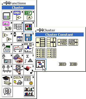
You can also simply pop up on a Cluster Terminal > Create > Constant.
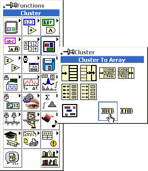
Cluster/Array Conversion
Converting Clusters To Arrays
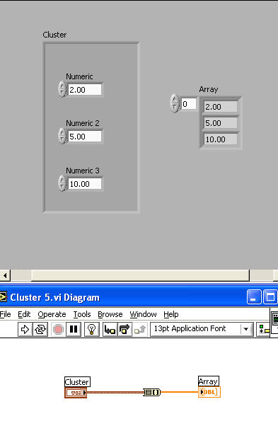
You can convert a cluster to an array if all cluster components have the same data type (all boolean, all numeric, etc.). The Cluster to Array function is found by popping up on the Block Diagram > Cluster > Cluster to Array.
Shown below is an example of a cluster control and an array indicator each of which contain three numeric controls. The Cluster to Array function is utilized on the block diagram to convert and transfer the data between them:
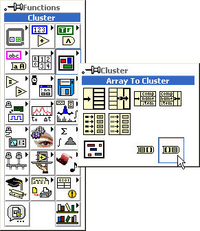
Converting Arrays to Clusters
As you may have expected, there is an Array to Cluster function to perform the opposite conversion. The Array to Cluster function is found by popping up on the Block Diagram > Cluster > Array to Cluster: