The Waveform Chart Indicator
Definition
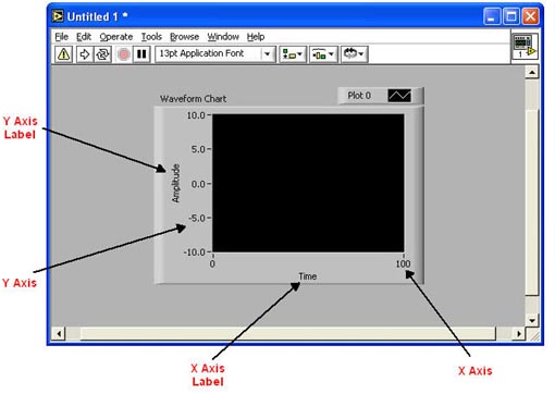
The Waveform Chart is a numeric indicator that displays one or more plots of scalar data. The plots are usually generated from inside loops. They display and retain data that has been acquired and append new data as it is acquired. The Y values represent new data and the X values represent time. The Y and X scale ranges can be modified to fit data values by editing the text on the Y and X scales.
How to Create a Waveform Graph
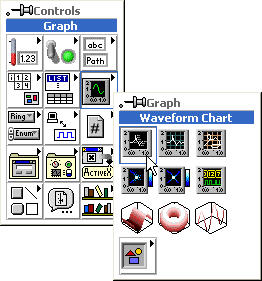
Pop-up in the Block Diagram > Controls > Graph > Waveform Graph:
Waveform Chart Update Display Modes
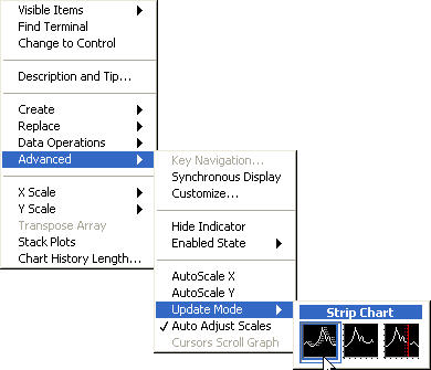
The waveform chart has three update display modes:
- Strip chart mode- The display continues to scroll to the right like a paper strip chart. When the data reaches the right side of the display, data on the left disappears.
- Scope chart mode - When the data plot reaches the right side of the display, the display goes blank and starts over from the left side of the display.
- Sweep chart mode - Is like the scope chart, but when the data plot reaches the right side of the display, a moving vertical line that moves across the display marks the beginning of new data.
These modes are accessed by selecting the Advanced > Update Mode menu when you pop-up on the Waveform Chart:
Waveform Charts With Multiple Plots
For waveform charts to accommodate more than one scalar-data plot, you must bundle the scalar data together using the Bundle function. The bundle function groups data (even different types of data) into one data type called a Cluster. It is analogous to putting many small wires into one big cable like a telephone cable with the outer cable being the cluster.
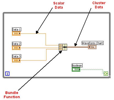
The Bundle function is found by popping-up in the Block Diagram > Functions > Cluster > Bundle:

Shift Registers
Definition
Shift registers are added variables available for both While Loops and For Loops that store and transfer values from one loop iteration to the next. A shift register is composed of a pair of terminals that lie horizontally opposite of each other on the vertical sides of the loop border. At the completion of each iteration, the right shift register terminal stores the data result(s) from that iteration. At the beginning of the next iteration the data is shifted to the left shift register terminal where the next iteration uses that value as its input data value. Data is not output from the loop until the completion of all loop iterations.
Shift registers can hold any data type and will automatically adjust to the initial data type of the node it is wired to.
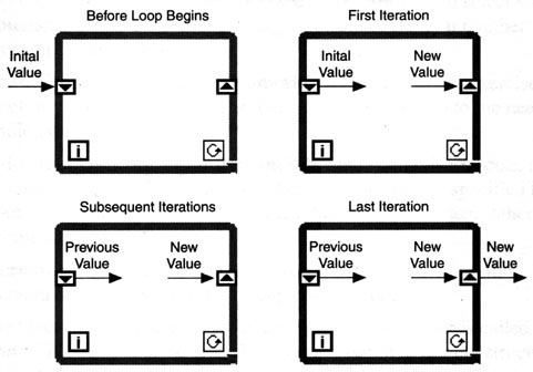
Below is an example of a For Loop with shift registers. It is programmed for 10 iterations (0 - 9) and adds the value of each iteration to the shift register value at each iteration. Note that the shift register value does not change until the beginning of the next iteration and that the final output is not sent out of the loop to the left-most indicator until the loop has completed all of its programmed iterations. Also note that the left shift register has been initialized to zero with a numeric constant. This is important because if the shift register is not initialized, it will default to the value for the shift register data type when you first run the VI.
Here's the Math. Notice how the shift register value always lags by one iteration because it doesn't get the data until the beginning of the subsequent loop.
Iteration |
Shift Register Value |
Addition Output |
Final Output |
0 |
0 |
0 |
0 |
1 |
0 |
1 |
0 |
2 |
1 |
3 |
0 |
3 |
3 |
6 |
0 |
4 |
6 |
10 |
0 |
5 |
10 |
15 |
0 |
6 |
15 |
21 |
0 |
7 |
21 |
28 |
0 |
8 |
28 |
36 |
0 |
9 |
36 |
45 |
0 |
End |
Of Last |
Iteration |
45 |
How to Create Shift Registers
To add a shift register to a loop, pop-up on the left or right vertical border of a loop > Add Shift Register:
Adding Elements to Shift Registers
You can add additional shift registers to the left side of a loop to remember values from previous iterations. This is useful when you want to average data or store values of all iterations, not just the final result.
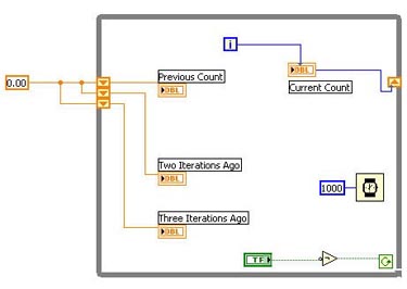
Below is an example of a while loop with two additional shift registers added to the left side of the loop. Notice that all three shift registers are initialized to zero with a numeric constant. Also notice that a boolean NOT function has been added between the boolean Stop button. This inverts the output of the stop button which has a default value of FALSE.
Creating Additional Shift Register Elements
To add additional shift register elements to a loop, pop-up on the left or right shift register of a loop > Add Element. You can also remove elements by popping-up on the desired element > Remove Element:

Controlling Boolean Controls
Mechanical Action
Boolean Controls usually operate like switches. Most of them are in the off position by default (Normally Open). You can control the mechanical action of the Boolean Control by popping-up on it > Mechanical Action:
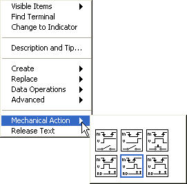
Below is a summary of the different mechanical actions for Boolean Controls. They are divided into two categories, Switch and Latch:
 |
Switch When Pressed - The Control's value is changed each time the control is pressed. This works much like a standard light switch. |
 |
Switch When Released - The Control's value is changed when the mouse button is released. |
 |
Switch Until Released - The Control's value is changed when the control is clicked and retains that value until the mouse button is released. |
 |
Latch When Pressed - The Control's value changes when it is clicked, retains that value until the VI reads it once and then reverts back to it's original value. |
 |
Latch When Released - The Control's value changes when the mouse button is released, retains that value until the VI reads it once and then reverts back to it's original value. |
 |
Latch Until Released - The Control's value changes when it is clicked, retains that value until the VI reads it once or until the mouse button is released, whichever occurs last. |
Showing a Boolean Controls State
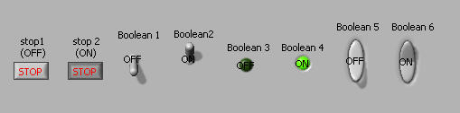
You can easily show a Boolean Control's On or Off state on the Front Panel by popping up on the control > Visible Items > Boolean Text:
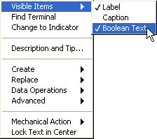
This will display OFF or ON on the controls with the exception of the STOP control:
|