The iv directory contains a copy of the inventor files used in this module. Try viewing each of them with ivview, for example ivview cone.iv. Gview is a great tool for manipulating the .iv files. To use gview you must have gview and gviewIcons.iv in the directory that you want to use them in. Both are already in the IV directory.
Click the image for a Larger View
| |
|
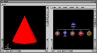
Let's start using gview by looking at cone.iv by typing gview cone.iv. Gview is comprised of two windows, the object display on the left and the nodal hierarchy on the right. This hierarchy reads from top to bottom and from left to right. Any change that you make will be inherited by the child and subsequent sibling nodes, thereby effecting anything below or to the right of where the change is made. Let's try to change the color of the sphere by selecting the material node. Double click on the node that is second from the right, the one with the red stripe. Change the diffuse color from red to green by changing the three numbers to 0 1 0. The properties of the other nodes can be changed in the same manner.
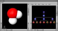
Water Molecule displayed in GView
 |
|
Try opening the next example, wm.iv, in gview. This is a representation of a water molecule. The first node in the nodal hierarchy is a group node. Double clicking on it will reveal that it is grouping three more group nodes together. Expand the group node in the middle and select the material node. Change the color in this group and notice what happens: both hydrogen atoms change color. The property was inherited by the second hydrogen, as discussed in the cone.iv example.
Robot Object displayed in GView
| |
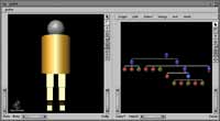 |
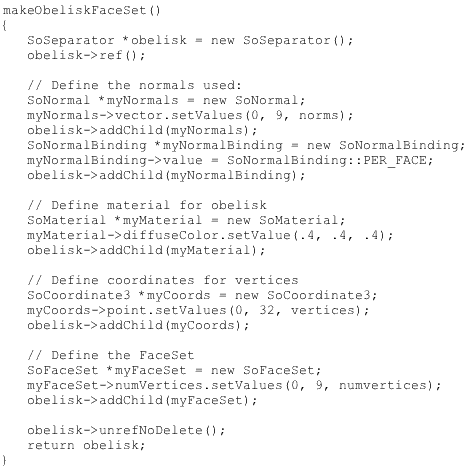
Next let's take a look at robot.iv. Here separator nodes are used to separate different parts of the robot. The robot is first separated into two groups, the head and the body. Upon expanding the separator node for the body you will see a translation node, a material node, a cylinder node (the torso) and two more separator nodes for each leg. Expand each of the separator nodes for the leg. Notice that the second shows a symbol that looks like an I. Double click on the symbol and it draws a line to the group creating the other leg, showing that it is a duplicate of that group. There are two ways to duplicate objects. First highlight the object that you want to duplicate and select edit. A menu will come down which will allow you to copy, paste, etc. In that menu you will also find duplicate and duplicate by reference. Under the separator for the head, select the sphere node (green with red square) and select, edit, duplicate. Place the duplicate at the beginning of the body separator node (to the left of the translation node that has two arrows on it). The robot now has a little butt. Double click on the sphere node for the head and change the radius. Notice that only the head changes size. Now delete the butt and follow the previous steps, selecting duplicate by reference. Upon changing the radius of the head this time, the butt will also change size.
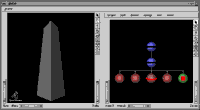
GView display of the Obelisk
|
|
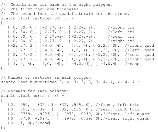
The obelisk is created by using normals and planes. To get an idea how this works, upon opening obelisk.iv, expand the separator node and click on the node farthest to the left. This is the node where all the normals are stored. Try scrolling down to the last normal (8): 0 -1 0. Try removing the negative and clicking apply. Notice that you no longer see the plane on the bottom of the obelisk. Use the navigation tools in the viewing window to get inside the obelisk and look down at the bottom plane. You can now see it from the inside. Next, bring up the Coordinate3 node, which is the second from the right. If you scroll to the bottom, you will see the last four points that define the bottom plane. They are numbered 28-31. Remove these points and the bottom plane will be completely removed.
One of the simplest ways to create an inventor file is by creating an object in Pro/Engineer and saving it as an inventor file. Try creating a unit cube in Pro/E. Sketch on the front plane with the right plane to the right. Sketch the square to be extruded with the bottom left corner at the intersection of the reference lines. Once the cube has been created click on file, save a copy as. Select the format as inventor (.iv). The next step is to ftp the .iv file that you created into the iv directory that you have been working in. Open the .iv file using gview. Now create a sphere using node, create, sphere. Place the node just to the left of the separator node. This will show us where the origin is. Notice that it is at one of the corners. If we wanted the center of the cube to be at the origin, there are two ways to adjust this. The first is to use a translation node. Insert a translation node between the sphere and the separator node (if you were to put it before the sphere, the sphere would be moved also). Adjust the location accordingly using the translation node (each direction should be either + or - 0.5). Also change the radius of the sphere to 0.65 so that both the cube and the sphere will be visible when centered. The other way to adjust where the cube or any object is located relative to the origin is to put it into an assembly in Pro-E and placing it in the desired location. Then save a copy of the assembly in the inventor format.
Chapter 2 (Cones)
We'll begin our discussion on Inventor using 4 examples of cones. These examples can be found within the inventor cones directory. The first thing that you will notice are all of the header files that are related to inventor. These header files contain the inventor functions that are used by this program.
Let's take a look at cone1.c++, beginning in main(). The first step in the program after the include files is to initialize inventor, which will return a window to use for the display.
Widget myWindow = SoXt::init(argv[0]);
if (myWindow == NULL) exit(1);
Next the scene is created, in this case a red cone. To create the scene, a root separator node needs to be created for use as the Inventor scene graph or nodal hierarchy. The scene graph will be just like the one we saw while using gview earlier, which consists of a group of nodes. Each node represents a geometry, property, or grouping object. Each node is created and added to the scene graph. The color of the material is also defined and in this case is set to red.
SoSeparator *root = new SoSeparator;
SoPerspectiveCamera *myCamera = new SoPerspectiveCamera;
SoMaterial *myMaterial = new SoMaterial;
root->ref();
root->addChild(myCamera);
root->addChild(new SoDirectionalLight);
myMaterial->diffuseColor.setValue(1.0, 0.0, 0.0); // RGB tripple 0 - 1.0
root->addChild(myMaterial);
root->addChild(new SoCone);
All that is left to do now is to display the scene that has been created. To do this, the render area is created. Then myCamera that was created above is set to view everything. The scene graph is then put into the render area. The last step is to display the main window.
SoXtRenderArea *myRenderArea = new SoXtRenderArea(myWindow);
myCamera->viewAll(root, myRenderArea->getViewportRegion());
myRenderArea->setSceneGraph(root);
myRenderArea->setTitle("Hello Cone");
myRenderArea->show();
SoXt::show(myWindow);
SoXt::mainLoop();
There are many different things that can be done to objects created in a scene. One thing that can be done is to make it spin. This is done in cone2.c++. To make the cone spin a rotation node is created and added to the scene graph. The rotation is then defined about the x-axis. myCounter is defined as the time that has elapsed since the program started and is connected to the angle field of rotation.
SoRotationXYZ *myRotXYZ = new SoRotationXYZ;
root->addChild(myRotXYZ);
myRotXYZ->axis = SoRotationXYZ::X;
SoElapsedTime *myCounter = new SoElapsedTime;
myRotXYZ->angle.connectFrom(&myCounter->timeOut);
Manipulators can also be added to a particular scene created in inventor. In cone3.c++ a trackball is added instead of the rotation node. A trackball allows the user to utilize the mouse to manually spin the cone. A trackball can be added in one line.
root->addChild(new SoTrackballManip);
It is also possible to move the camera around, instead of moving the cone itself. This is done by replacing the render area with an examiner viewer. Now the mouse can control where the camera is relative to the cone:
SoXtExaminerViewer *myViewer = new SoXtExaminerViewer(myWindow);
myViewer->setSceneGraph(root);
myViewer->setTitle("Examiner Viewer");
myViewer->show();
Chapter 3 (Nodes)
There are three different types of nodes. A shape node represents a geometric object. A property node controls the appearance and characteristics of the scene. As discussed in the water molecule example, a group node can be used to logically group related nodes. Each node consists of a set of data elements or fields that describe and control the parameters of the node. To better understand how nodes are used, let's look at the code used to create the water molecule example (wm.c++ in the nodes directory).
After the include files and the main routine is opened, the program begins just like the cone does:
Widget myWindow = SoXt::init(argv[0]);
if (myWindow == NULL) exit(1);
SoSeparator *root = new SoSeparator;
root->ref();
SoXtExaminerViewer *myViewer = new SoXtExaminerViewer(myWindow);
To begin to create the scene of a water molecule a group node is created called waterMolecule. Next the individual nodes used to create the water molecule will are created. For the oxygen atom a group node, a material node and a sphere node are created. A material node defines the surface material of all the shapes that follow it. The data elements that are used are ambientColor (reflected color of an object in response to the ambient lighting in the scene), diffuseColor (the base color), specularColor (reflective quality of an object's highlights), emmisiveColor (light produced by an object), shininess and transparency. The sphere node creates an object as a sphere.
SoGroup *waterMolecule = new SoGroup;
// oxygen atom
SoGroup *oxygen = new SoGroup;
SoMaterial *redPlastic = new SoMaterial;
SoSphere *sphere1 = new SoSphere;
When creating each hydrogen atom the same nodes are used with the addition of a transform node. A transform node contains the data elements translation (the translation along the x, y, and z axis), rotation (about an axis, at a specified angle), scaleFactor (one in each direction), scaleOrientation (the rotation to apply before the scale is applied) and center (the center point for rotation and scaling).
// hydrogen atoms
SoGroup *hydrogen1 = new SoGroup;
SoGroup *hydrogen2 = new SoGroup;
SoTransform *hydrogenXform1 = new SoTransform;
SoTransform *hydrogenXform2 = new SoTransform;
SoMaterial *whitePlastic = new SoMaterial;
SoSphere *sphere2 = new SoSphere;
SoSphere *sphere3 = new SoSphere;
Now, the properties are changed as needed using the data elements of each node:
// Set all field values for the oxygen atom
redPlastic->ambientColor.setValue(1.0, 0.0, 0.0);
redPlastic->diffuseColor.setValue(1.0, 0.0, 0.0);
redPlastic->specularColor.setValue(0.5, 0.5, 0.5);
redPlastic->shininess = 0.5;
// Set all field values for the hydrogen atoms
hydrogenXform1->scaleFactor.setValue(0.75, 0.75, 0.75);
hydrogenXform1->translation.setValue(0.0, -1.2, 0.0);
hydrogenXform2->translation.setValue(1.1852, 1.3877, 0.0);
whitePlastic->ambientColor.setValue(1.0, 1.0, 1.0);
whitePlastic->diffuseColor.setValue(1.0, 1.0, 1.0);
whitePlastic->specularColor.setValue(0.5, 0.5, 0.5);
whitePlastic->shininess = 0.5;
The scene graph then needs to be organized by grouping the various elements together. This is done by using addChild. First each atom is added to the waterMolecule group. Then each element of each atom is grouped with its corresponding atom.
// Create a hierarchy
waterMolecule->addChild(oxygen);
waterMolecule->addChild(hydrogen1);
waterMolecule->addChild(hydrogen2);
oxygen->addChild(redPlastic);
oxygen->addChild(sphere1);
hydrogen1->addChild(hydrogenXform1);
hydrogen1->addChild(whitePlastic);
hydrogen1->addChild(sphere2);
hydrogen2->addChild(hydrogenXform2);
hydrogen2->addChild(sphere3);
Now the scene is ready to be displayed; it is displayed just like the cone:
myViewer->setSceneGraph(waterMolecule);
myViewer->setTitle("Examiner Viewer");
myViewer->show();
SoXt::show(myWindow);
SoXt::mainLoop();
The other example to look at for nodes is robot.c++. The main difference between the water molecule and the robot is the use of the SoSeparator node. An SoSeparator node is a subclass of SoGroup and isolates the effects of the nodes within the group so that they only effect that particular group. A few more shapes are also introduced in the robot.
Chapter 5 (Shapes)
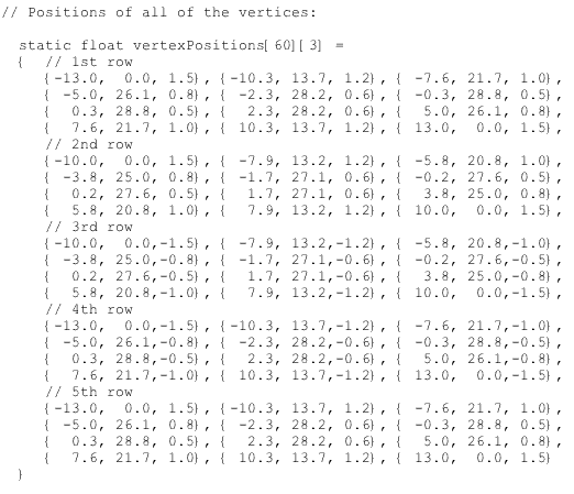
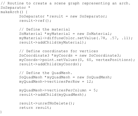
It is possible to make an object of any shape in inventor. Inventor provides many different nodes to create these shapes. There are four specific simple shapes that inventor provides. These shapes are all found in the previous examples, cube (width, height, and depth are specified), cone (the height and bottom radius are specified), sphere (the radius is specified) and cylinder (the height and the radius are specified). All other shapes need to be created by inventor's complex shape nodes. Two of the most commonly used complex shape nodes are face set and quadmesh. In the Shapes directory the two examples, obelisk.c++ and arch.c++ illustrate these two complex shape nodes.
The obelisk is created using the face set node(SoFaceSet). To use the face set node, each face created needs to have a normal vector defined ,the number of vertices it will use, and the coordinates for each of its vertices defined.
The arch is created using the quadmesh node(SoQuadMesh). This node creates a scene by constructing quadrilaterals from the specified vertices, starting with the first vertex unless one is specified in the startIndex field. The number of vertices in each row and column can be defined by the verticesPerColumn and verticesPerRow fields.
Files (Controlling Inventor)
Once you have created the scene, by either creating it from scratch or importing an already existing inventor file, you want to control how the scene is changing. The following examples found in the FILES/ directory demonstrate different ways that this can be done.
The first example, in the files1/ directory shows how a preexisting file can be accessed by a c++ program. Once you have compiled my_viewer, you can use the program to view any of the inventor files in the directory. This is done by typing the following command at the prompt:
> my_viewer filename.iv
This program acts just like ivview. The program takes the second argument made and assigns it to name.
strcpy(name, *(argv + 1));
Then the file is opened and put into the scene.
mySceneInput->openFile(name);
root = SoDB::readAll(mySceneInput);
mySceneInput->closeFile();
The rest of the file is the same as we have seen in previous sections.
Now we can start to make some changes to the scene while we are viewing it. In the files2/ directory my_viewer has been changed so that it can modify assembly.iv using values that are entered by the keyboard. Now the program will open assembly.iv without a second argument being made when the program is run. The line strcpy(name, *(argv + 1)); was removed and the following line was modified to read as follows:
mySceneInput->openFile("assembly.iv");
When run, the program will ask for a displacement for the cube and the cylinder. Once the values are entered, the scene will be updated and you will actually see the cube and cylinder move. The translation nodes for both the cube and the cylinder are accessed, with the new values for translation of in the x direction being assigned using the method below.
printf("type in a displacement for cube and then cylinder\n\");
scanf("%f%f", &cubet, &cylt);
cube->translation.setValue(cubet, 0.0, 0.0);
cylinder->translation.setValue(cylt, 0.0, 0.0);
Click here to move on to the next section (Apply). |