Navigate back to the activity.
Three sinusoidal voltages: Instructor's Guide
Main Ideas
Interpretation of graphical information in the context of resonant response.
Students' Task
Estimated Time:10 minutes
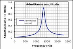
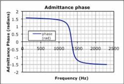
The students were given two different graphs and were asked to graph the driving voltage, $V(t) = V_0 e^{i(2 \pi f + \phi_{voltage})}$ for specific frequencies, magnitudes, and phases (Each group were assign different frequencies, magnitudes, and phases).
Prerequisite Knowledge
- LRC circuit
Props/Equipment
- Tabletop Whiteboard with markers
- A handout for each student osthreesindrivershand.pdf
Activity: Introduction
Students from groups, and each group is asked to predict, semi-quantitatively, the current in the series LRC circuit, based on the two response curves given (admittance vs. frequency, and phase vs. frequency). They are to draw the oscilloscope traces representing (i) the driving voltage and (ii) the voltage across the resistor (proportional to the current) with due attention to size and phase. Because these are from the lab that they have just done, no further introduction is needed. Students are instructed to move onto the other assigned frequencies if they finish early. The results should be on the large whiteboard, with axes labeled appropriately.
Activity: Student Conversations
Students usually take several minutes to establish that they must multiply the magnitude of the driving voltage by the value shown on the admittance amplitude graph and shift the phase by the value indicated on the phase graph, at the relevant frequency. Many are not sure what to do at all; others grasp the magnitude aspect but simply ignore the phase.
Activity: Wrap-up
Each group shows its results, and we discuss interpretation of graphical information. We discuss as a large group the result of the superposition voltage driver, and with the individual responses displayed graphically, it is quite easy to see that the non-resonant components are dominant.
This is a good time to discuss how small signals can be present at one frequency, but swamped by a larger signal at another frequency. Filters could remove the large signal, revealing the small, interesting one.
Extensions
Students are asked to consider what the voltage across the resistor (i.e. the current) would be if all three voltage signals were added and applied simultaneously. The responses are varied: (i) The correct response is usually a minority response, namely that the current would be a superposition of the three currents found, and that it is a (ii) A sawtooth-shaped current (iii) A sinusoidal current with small sinusoidal variations superimposed (iv) A single sinusoid
(At this point the linearity of the differential equation has not been explicitly discussed.)

